Cookies help us deliver our services. By using our services, you agree to our use of cookies.
From the same category
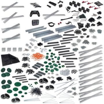
VEX V5 Competition Super Kit 2767100 (1) 2767004 (1)
VEX 2767140
The perfect all-in-one kit for any newVEX Robotics Competition teamor an existing team looking to supercharge their robot.
This kit contains everything needed to get up and running with theV5 Control System, along with a variety of aluminum structural parts to build lighter and faster mechanisms, and theVision Sensorto see the competition from a whole new perspective.
Compete with over 11,000 worldwide VEX Robotics Competition teams
Build powerful mechanisms with the high strength gears, sprockets, and shafts included
Scalable programming software suite available with VEXcode
€2295.00
VEX V5 Competition Starter Kit was 2766610 (2767100 + 2767003)
VEX 2767130
Take educational robotics to the next level by competing in the VEX Robotics Competition. The only limit to this open-ended building system is your own imagination!
The V5 Competition Starter Kit includes a complete V5 control system, aluminum structural elements, and high strength parts so that a team of students can build a bigger, stronger, and faster robot.
Compete with over 11,000 worldwide VEX Robotics Competition teams
Lightweight aluminum structure designed specifically for competition
Scalable programming software suite available with VEXcode
Recommended one competition team per kit.
€1395.00
VEX V5 System Bundle
VEX 2767100
Take your VEX robot to the next level with the V5 System Bundle. This bundle includes everything you need to get started with V5, and is engineered to provide the most advanced robotics experience, right at your fingertips.
Designed to scale from the classroom to the competition field
Includes all necessary components to get started with the V5 System
Scalable programming software suite available with VEXcode
Designed to scale from the classroom to the competition field
Includes all necessary components to get started with the V5 System
Scalable programming software suite available with VEXcode
€968.99
VEX V5 Pneumatics Kit
VEX 2768750
This kit contains everything needed to get a classroom or VEX Robotics Competition team up and running with Pneumatics.
Pneumatics deliver fast and powerful linear motion that is useful in a variety of applications. Use pneumatics to power your robot's claw, intake deployment, or any mechanism that requires quick motion. In particular, pneumatics are useful in applications requiring only two positions (open/closed, up/down, etc.)
V5 Pneumatics Kit Contains:1 x Pneumatic Tubing Cutter 1 x Dual Acting Cylinder, 10mm Bore, 25mm Stroke 1 x Dual Acting Cylinder, 10mm Bore, 50mm Stroke 1 x Dual Acting Cylinder, 10mm Bore, 75mm Stroke 1 x 4mm OD x 2.5mm ID PU Tubing (3m) 1 x Pneumatic Reservoir 1 x Pneumatic Hand Valve 2 x Double Action Solenoid Wire 2 x Dual Acting V5 Pneumatics Solenoids 1 x Pressure Regulator 1 x Pressure Regulator Bracket 1 x Pressure Regulator Pressure Gauge 1 x Pressure Gauge 10 x Straight Pneumatic Fittings 8 x 90 Deg. Elbow Pneumatic Fittings 5 x "T" Pneumatic Fittings 2 x 90 Deg. Elbow Pneumatic Fitting (Flow Control, M5, 4mm Hose) 10 x Pneumatic Fitting Plug 1 x Schrader Valve 1 x Straight Pneumatic Fitting (M5 Female, 4mm Hose) 2 x Manifold Assemblies
Pneumatics deliver fast and powerful linear motion that is useful in a variety of applications. Use pneumatics to power your robot's claw, intake deployment, or any mechanism that requires quick motion. In particular, pneumatics are useful in applications requiring only two positions (open/closed, up/down, etc.)
V5 Pneumatics Kit Contains:
€385.00
VEX V5 Robot Brain
VEX 2764810
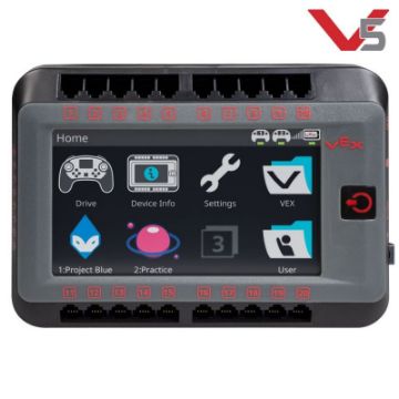
Everything starts with the V5 Robot Brain. Students and teachers can now run programs, troubleshoot their robot and get important feedback in real-time. Smart Ports automatically detect the type of connected device and handle motors and sensors interchangeably.
Other features include: 4.25” (108mm) full colour touch-screen Dashboards provide real-time diagnostics 21 Smart Ports Eight 3-Wire ports for analog and digital sensors Download programs wirelessly Programmable with VEXcode
Other features include: 4.25” (108mm) full colour touch-screen Dashboards provide real-time diagnostics 21 Smart Ports Eight 3-Wire ports for analog and digital sensors Download programs wirelessly Programmable with VEXcode
€460.00
VEX V5 Controller
VEX 2764820
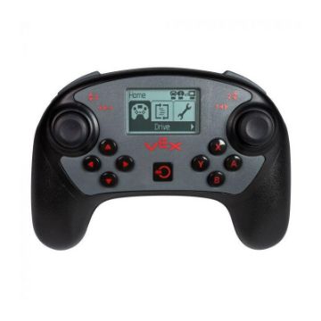
Control your robot like never before with the cutting-edge V5 Controller. This controller packages two analog joysticks and 12 buttons into a familiar video-game style design. A rechargeable battery ensures enough charge to get you through multiple class periods or a full day of competition.
Other features include:LCD Screen for real-time information Start and stop programs from the controller Programmable haptic feedback Competition practice mode - sync up with other robots and run practice matches Built-in VEXnet 3.0 radio and Bluetooth® Integrated rechargeable battery
Other features include:
€172.95
VEX V5 Robot Battery Li-Ion 1100mAh
VEX 2764811
The V5 Robot Battery Li-Ion 1100mAh is the next evolution of the VEX EDR NiMh Battery, which will provide you consistent performance every time you power up your robot. This Lithium Iron Phosphate (LiFePO4) battery is equipped with circuitry and control to allow for higher sustained power and more reliable function. The V5 System as a whole is designed to produce identical motor performance at any battery charge level. This means that the same battery can be used for multiple competition matches or class periods before needing to be recharged. LiFePO4batteries are proven to offer longer life cycles, and are safer than Lithium Ion batteries.
Battery run time depends on many factors including your robot design, your driving, and the number of motors used. Robots' often get 30+ minutes of heavy drive time from a single charge. Competition teams should be able to use one Robot Battery for multiple matches without recharging. Remember that with V5, a low battery does not change the motor's performance.
Built-in charge indicator lights Charge time is approximately one hour Note: Battery power cable and charger not included. (Power cable ships withV5 Robot Brain)
Battery run time depends on many factors including your robot design, your driving, and the number of motors used. Robots' often get 30+ minutes of heavy drive time from a single charge. Competition teams should be able to use one Robot Battery for multiple matches without recharging. Remember that with V5, a low battery does not change the motor's performance.
€110.00
VEX V5 Vision Sensor
VEX 2764850
Give your driver the chance to see things from the robot's perspective. The Vision Sensor is capable of detecting up to 7 colors at once, including multi-colored objects. Connect a phone or tablet to the V5 Robot Brain through built-in WiFi to stream a live feed of your robot's view to your device.
Other features include:
Tracks up to seven individual colors at once
Analyze objects for advanced tracking and path planning
Built-in Wi-Fi radio
Compatible with VEX IQ
The Vision Sensor provides a robot with new capabilities and allows for expanded learning. It uses a dual ARM M4/M0 processor for object detection at 50Hz. At its most basic mode it tells you where a colored object is located. The location's X value gives you the position right and left. When the camera is tilted down, the Y value gives you the distance to the object, with a little basic trigonometry on your part.
€117.94
VEX V5 Smart Motor 36:1 Cartridge (100 RPM)
VEX 2765840
Gear Options
Mechanisms such as flywheels and arms do not need large external gear ratios when the driving motor is already outputting a targeted output speed or torque. Therefore, changing internal gear ratios to fit specific needs allows more efficient and compact mechanisms to be designed. Use the clear window of the V5 Smart Motor to identify one of three user-changeable colored gear cartridges:
36:1 (100 RPM)- High torque, low speed. Great for robot arms and lifting heavy objects
€17.24
VEX Field Perimeter Rubber Foot (20-pack)
VEX 2765156
Give your field a leg up. These rubber feet are distributed along the bottom edges of a VEX Robotics Competition field perimeter, thereby raising it to the same height as the field tiles. No more cutting tiles!
Compatible with VEX V5 products and accessories
Compatible with VEX V5 products and accessories
€16.49


